The ESP32 Wroom Dev Mod, also known as the ESP32 DevKitC, is a popular development board designed for the ESP32 microcontroller. This board provides a comprehensive set of features, including Wi-Fi, Bluetooth, and a range of GPIO pins, making it an ideal choice for IoT projects, robotics, and other applications that require wireless connectivity and versatile I/O capabilities. Understanding the pinout of the ESP32 Wroom Dev Mod is crucial for effectively utilizing its capabilities and integrating it into various projects.
Introduction to the ESP32 Wroom Dev Mod Pinout

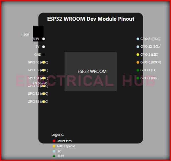
The ESP32 Wroom Dev Mod pinout is designed to provide easy access to the ESP32’s capabilities. The board features a 38-pin layout, with pins arranged in two rows of 19 pins each. This layout includes power supply pins, communication interface pins (such as UART, SPI, I2C, and I2S), GPIO pins, and dedicated pins for the board’s built-in peripherals like the USB interface and the reset button.
Power Supply and Reset Pins
The power supply to the ESP32 Wroom Dev Mod is typically provided through the USB port, which also facilitates communication with a computer for programming purposes. The board requires a 5V power supply, and it includes a voltage regulator to step down the voltage to the levels required by the ESP32 (3.3V). Key power-related pins include:
- VUSB (5V): Directly connected to the USB port and used for powering the board when connected to a computer or a USB power adapter.
- EN (Enable): Connected to the voltage regulator’s enable pin. This pin is used to control the power supply to the ESP32 module.
- GND (Ground): Multiple ground pins are available for connecting external components to the ground reference.
- 3V3 (3.3V): The regulated 3.3V output from the voltage regulator, which can be used to power external components.
- 5V: Direct access to the 5V supply before the voltage regulator.
Communication Interface Pins
The ESP32 Wroom Dev Mod provides several communication interfaces, including UART, SPI, I2C, and I2S. These interfaces are crucial for communicating with other devices, sensors, and peripherals.
- UART: The board has a dedicated UART interface, which is typically connected to the USB-to-serial converter chip (like the CP2104) for programming and serial communication. The UART0 pins (TX0 and RX0) are usually connected to the USB-to-serial converter.
- SPI: The ESP32 supports SPI communication, with dedicated pins for MISO, MOSI, SCK, and SS (Slave Select). These pins can be used to communicate with SPI peripherals.
- I2C: I2C communication is supported with pins dedicated for SCL (Clock) and SDA (Data). These pins facilitate communication with I2C devices.
- I2S: For audio applications, the ESP32 provides an I2S interface, which can be used for communication with audio codecs or other I2S-compatible devices.
GPIO Pins
The majority of the pins on the ESP32 Wroom Dev Mod are GPIO (General Purpose Input/Output) pins. These pins can be configured as digital inputs or outputs and can also be used for various peripheral functions, such as SPI, I2C, I2S, UART, and more, due to the ESP32’s multiplexing capability.
A key aspect of the ESP32 GPIO pins is their ability to be used for multiple functions, a concept known as pin multiplexing. This means that a single pin can be configured for different functions, depending on the application’s requirements. For example, a pin might be used as a simple digital output for driving an LED in one project and as part of an SPI interface for communicating with a sensor in another.
| GPIO Pin | Description |
|---|---|
| GPIO0 | Can be used for button press detection during boot to enter flash mode. |
| GPIO2 | Connected to the built-in LED on the board. |
| GPIO12 - GPIO15 | Typically used for the HSPI (High-Speed SPI) interface. |
| GPIO16 - GPIO17 | Can be used for I2C or as GPIO. |

Key Points
- The ESP32 Wroom Dev Mod features a 38-pin layout, providing access to a range of peripherals and interfaces.
- The board supports Wi-Fi, Bluetooth, and various communication interfaces, including UART, SPI, I2C, and I2S.
- GPIO pins on the ESP32 can be configured for multiple functions due to pin multiplexing, enhancing the board's versatility.
- Understanding the pinout is crucial for effectively using the ESP32 Wroom Dev Mod in projects, ensuring proper connection of peripherals and configuration of communication interfaces.
- Consulting the official documentation and datasheet is recommended for detailed pinout information and to leverage the full potential of the ESP32 microcontroller.
Practical Applications and Considerations

The ESP32 Wroom Dev Mod’s versatile pinout and robust set of peripherals make it suitable for a variety of applications, from simple IoT devices to complex robotics projects. When integrating the ESP32 into a project, considerations such as power supply, communication protocols, and peripheral selection are crucial for optimal performance and reliability.
Power Supply Considerations
Given the ESP32’s power requirements, selecting an appropriate power supply is essential. The board can be powered via the USB port or through the VIN pin, which allows for an external power source. Ensuring that the power supply can provide sufficient current, especially in projects with multiple peripherals, is vital to prevent power-related issues.
Peripheral Selection and Configuration
The choice of peripherals (such as sensors, displays, or actuators) depends on the project’s requirements. Each peripheral has specific communication and power requirements, which must be compatible with the ESP32’s pinout and capabilities. Proper configuration of GPIO pins for the selected peripherals is also necessary to ensure correct functionality.
What is the primary difference between the ESP32 Wroom Dev Mod and other ESP32 development boards?
+The primary differences often lie in the specific features, such as the type of USB-to-serial converter used, the availability of certain peripherals (like buttons, LEDs, or USB OTG), and the physical layout and size of the board. The ESP32 Wroom Dev Mod is known for its compact size, comprehensive set of features, and ease of use.
How do I program the ESP32 Wroom Dev Mod?
+Programming the ESP32 Wroom Dev Mod typically involves using the Arduino IDE or the ESP-IDF framework. The board connects to a computer via USB, and the chosen development environment is used to write, compile, and upload code to the ESP32 microcontroller.
What are some common applications of the ESP32 Wroom Dev Mod?
+Common applications include IoT devices, home automation systems, robotics, wearables, and industrial control systems, leveraging the ESP32's wireless communication capabilities, peripheral interfaces, and small form factor.
In conclusion, the ESP32 Wroom Dev Mod offers a powerful and flexible platform for a wide range of applications, thanks to its comprehensive pinout, wireless communication capabilities, and extensive set of peripherals. By understanding the pinout and capabilities of the ESP32 Wroom Dev Mod, developers can unlock its full potential and create innovative, connected devices that meet the demands of modern IoT and robotics projects.